Information about Gas Springs and their Application
Gas spring forces.
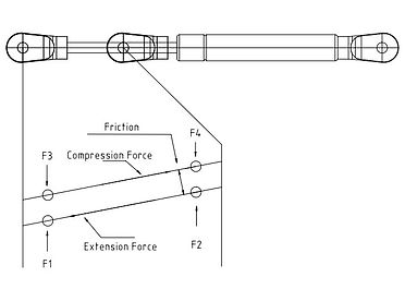
When you order a gas spring you specify the F1 force, or with some manufacturers a P1 force. With this module I wanted to explain exactly what an F1 force is and what the difference is with a P1 force. To the right you will see a graphic representation of the forces exerted by a gas spring. There are different points labeled on the stroke. They are measure at points 5mm from the end and beginning of the stroke.
For example the F1 force is the force measured as the rod is extending measured 5mm before
the end of the stroke. The F3 force is measured at the exact same location as the F1
force, but it is measured as the rod is being compressed. The difference is caused by the
friction of the seal package on the rod. Some manufacturers refer to a P1 force. This force
is measured at the exact location as the F1 and F3 force is measured at, 5mm from the end
of the stroke, but it is a static measurement. It is taken when the rod is not moving at all. So
the friction is not taken into account at all. So on this graph it would be located between
the F1 anf F3 force. So, if we had a gas spring with a P1 force of 100N, and the seal package
created a resistance of 5 N, then what would the F1 and F3 forces be? Well, on extension, at
a point 5mm from the end of stroke, the rod would be moving out with a force of 100N, but
the seal package would take 5N just to allow the rod to move, so the net output force, or
F1 would be 95N. Now when you compressed the rod at the same point you would have to
generate the 100N to overcome the P1 force, plus an additional 5N to overcome the seal
package, so the F3 force would be 105N. Hence the difference in measurements. For the
vast majority of applications this difference is so small that it can be ignored, but for some
springs and some applications it must be taken into account, so the manufacturers provide
the information. When I designed GASSIM I added the capability to take this into account. You will see a box labeled "friction" in GASSIM where the user can input the friction of the seal package. If it is unknown I usually place a value which is around 10% of the F1 force. This is usually sufficient in the case of most springs. You will also notice on the force graph that the force increases as the spring is compressed. This is the difference between F1 and F2, or F3 and F4. This rise is caused by the rod being inserted in the tube. As more of the rod is placed in the tube, the volume in the tube is reduced, so the nitrogen is compressed more. This increase in force is called the spring's "progression", "force ratio", or "K-factor" depending on the manufacturer you are talking to. This must be accounted for when fitting gas springs into an application. In GASSIM I labeled this value "force ratio". The usual force ratio for a gas springs is around 1.2 - 1.3 this is the area most manufacturers seem to shoot for. This means that F2/F1 = 1.3 Or if the F1 force is 100N, then the F2 force will be 130N. This can vary though. Some larger springs might be 1.4-1.5. Some special springs use larger tubes and smaller rods to get force ratios like 1.05. It depends on what is needed in the application. This usually isn't a problem as engineers who specify gas springs know how to manipulate the geometry of the mounting points to account for this progression. If you are struggling with this problem contact me and I will be glad to help you out.